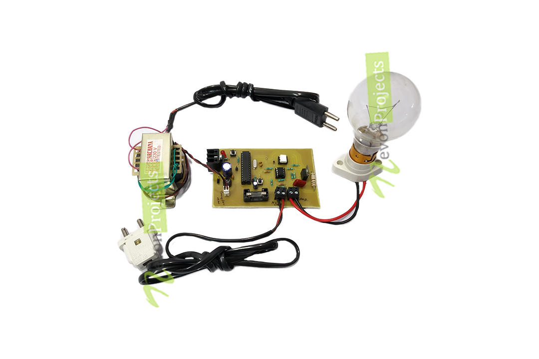

It controls output by sensing the voltage V-out at a power-generating coil and comparing it to a stable reference.
AVR CONTROL SYSTEM GENERATOR
Explanation of Voltage Regulation of Transformer: Say an electrical power transformer is open circuited, means load is not connected with secondary terminals.Īn automatic voltage regulator (AVR) is an electronic device for automatically maintaining generator output terminal voltage at a set value under varying load and operating temperature.
AVR CONTROL SYSTEM FULL
The voltage regulation is the percentage of voltage difference between no load and full load voltages of a transformer with respect to its full load voltage. The function of the Automatic Voltage Regulator (AVR) is to maintain constant voltage and power line conditioning to the equipment load under a wide variety of conditions, even when the utility input voltage, frequency or system load vary widely. The variation in the voltage can be controlled by installing the voltage control equipment at several places likes near the transformers, generator, feeders, etc., The voltage regulator is provided in more than one point in the power system for controlling the voltage variations.ĪVR – to take a fluctuating voltage level and turn it into a constant voltage level. The variation in voltage damages the equipment of the power system. The fluctuation in the voltage mainly occurs due to the variation in load on the supply system.

It takes the fluctuate voltage and changes them into a constant voltage. In this way, you can control DC motors using AVR.The automatic voltage regulator (AVR) is a device designed to regulate voltage automatically.

He used the eXtreme Burner for burning the code. He has used the low cost 28 pin AVR Development Board and the USBasp AVR Programmer by eXtreme Electronics. The video is made by Lavin Khandelwal for ma圎mbedded. This is a simple demonstration of controlling two DC motors using a single L293D IC and a microcontroller.
AVR CONTROL SYSTEM CODE
The code can also be found on pastebin and in the code gallery.Īfter burning the code into your MCU, you will find that the motors rotate in clockwise direction for 0.5s and counter-clockwise direction for 0.5s. If you are new to AVR Studio 5, you can read this post to get started with it. Now open up AVR Studio 5, type the following code and build it. Assuming ATMEGA32, let us connect L293D across PORTC pins (PC0…PC3) as shown in the diagram below. Now let’s generate control signals from the AVR MCU and feed them to the inputs of L293D. Enabling both pins at the same time will drain your battery unnecessarily. Suppose if you need to control only one motor at a time, you need to enable that particular EN pin. M2-A = 0 and M2-B = 1 → M2 moves counter-clockwise.M2-A = 1 and M2-B = 0 → M2 moves clockwise (say).M1-A = 0 and M1-B = 1 → M1 moves counter-clockwise.M1-A = 1 and M1-B = 0 → M1 moves clockwise (say).Now consider the following cases for motor M1: Connect pin 16 to Vcc (=5V) and pin 8 to Vs (battery, 4.5V~36V).Īs per the diagram, the inputs of motor M1 are M1-A and M1-B, whereas inputs of motor M2 are M2-A and M2-B.Connect GROUND pins 4, 5, 12 and 13 to ground.The inputs for motor M2 is given across INPUT3 and INPUT4 i.e.The inputs for motor M1 is given across INPUT1 and INPUT2 i.e.Connect motor M2 across OUTPUT3 and OUTPUT4 i.e.Connect motor M1 across OUTPUT1 and OUTPUT2 i.e.Pin 1 EN enables the motor M1 whereas pin 9 EN enables motor M2. There are two enable (EN) pins, pin 1 and pin 9.In this way, we can have bidirectional control over two motor.


 0 kommentar(er)
